CG Science for Artists Part 2: The Real-Time Rendering Pipeline
Welcome to the second part of my series on the Science of Computer Graphics for artists. My goal with this series is to go through the underlying science behind computer graphics so that you have a better understanding on what’s happening behind the scenes. I’d like to take potentially complex concepts and present them in a way that is approachable by artists.
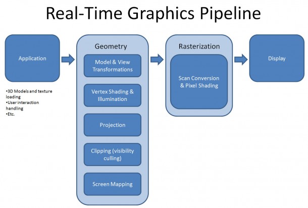
This tutorial is a high-level overview of a basic real-time rendering pipeline. As we mentioned in our last article, real-time simply means that it is doing the rendering immediately (hopefully above 30fps).
The pipeline we’re covering is the same basic pipeline used for everything from video games on your iPhone to consoles and the viewports in your CG application. Whether you model something in a 3D application and see the viewport updating, or run around a virtual environment in your game, it is going through a similar graphics pipeline in the background.
What is the purpose of a rendering pipeline?
Essentially, the whole purpose of 3D computer graphics is to take a description of a world comprising of things like 3D geometry, lights, textures, materials, etc. and draw a 2D image. The final result is always a single 2D image. If it’s a video game, it renders 2D images at high frame rates. At 60fps, it’s rendering one image every 1/60th of a second. That means that your computer is doing all these mathematical calculations once every 60th of a second. Yes… that’s a lot of calculations. I hope you can appreciate that.
The reason for pipelining is the same as what Henry Ford did when he first manufactured Model T’s. Once one process is done, it can pass the results off to the next stage of the pipeline and take on a new process. In the best-case scenario, this streamlines everything as each stage of the pipeline can work simultaneously. The pipeline can slow down if a stage of a pipeline takes longer to process. This means that the entire pipeline really can only run at the speed of the slowest process.
The pipeline
Stages of the pipeline:
- Application – anything that the programmer wants. Interactions, loading of models, etc. Feed scene information into Geometry stage.
- Geometry – Take scene information and transform it into 2D coordinates
- Modeling transformations (modeling to world)
- View transformations (world to view)
- Vertex shading
- Projection (view to screen)
- Clipping (visibility culling)
- Rasterization – Draw pixels to a frame buffer
- Display
Application Stage
The Application stage of the pipeline is pretty open and left to programmers and designers to figure out what they want the application or game to do. The end result of the application stage are rendering primitives such as vertices/points, triangles, etc. that are fed to the next (Geometry) stage. At the end of the day, all that beautiful artwork that you’ve created is just a collection of data to be processed and displayed.
Some things that are useful for the application stage would be user input and how this affects objects in a scene. For example, in your 3D application, if you were to click on an object and move it, it needs to figure out all the variables: what object you want to move, by how many units, what direction. It’s the same in a video game. If you have a character and move the view, the application stage is what takes user input such your mouse positions and figures out what angle the camera should rotate.
Another thing about the application stage is loading of assets. For example, all the textures and all the geometry in your scene needs to be read from disk and loaded into memory, or if it’s already in memory, be manipulated if needed.
The Geometry Stage
The basic idea of the geometry stage is: How do I get a 3D representation of my scene and turn it into a 2D representation? Note that at this point in the pipeline, it hasn’t actually drawn anything yet. It’s just doing “transformations” of 3D primitives and turning them into 2D coordinates that can be fed into the next stage (Rasterization) to do the actual drawing.
Model and View Transformations
The idea behind Model and View Transformations is to place your objects in a scene, then view it from whatever angle and viewpoint you’d like. Modeling and Viewing Transformations confuse everyone new to the subject matter. I’ll do my best to make it simple. Let’s use the analogy of a taking a photograph.
In the real world, when you want to take a photograph of an object, you take the object, place the object in your scene, then place a camera in your scene and take the photo.
In graphics, you place the objects in your scene (model transform), but the camera is always at a fixed position, so you move around the entire world (view transform) so that it aligns to the camera at the distance and angles that you want, then you take the picture.
Taking a photo in the real world, vs the CG world
| Step | Real world | CG world | CG term |
| 1 | Place objects (e.g. teapots, characters, etc. at various positions) | Place objects (e.g. teapots, characters, etc. at various positions). | Model transform |
| 2 | Place and aim camera. The world is fixed. You move the camera into position. | Transform the entire world to orient it to the camera. The camera is fixed. The world transforms around it. | View transform |
| 3 | Take the photo | Calculate lighting, projection, rasterize (render) the scene. | Lighting, Projection, Rasterization |
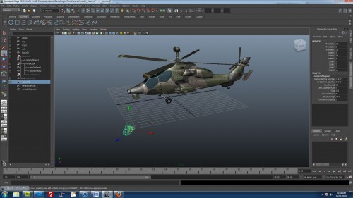
In general, people like to use the "photography" analogy to view 3D scenes by placing a camera at a position in world space. For example, we can rotate the camera on the y axis and translate it away from the object.
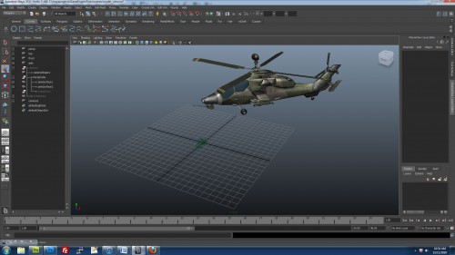
In the computer, however, what it's actually doing is transforming all the vertices in the scene. There is no concept of a separate camera view. The camera is always "stationary" and everything transforms around the camera. What it's doing here is rotating all the vertices in the scene then moving them away from the camera. The resulting view is exactly the same.
Now you’re wondering, “that can’t be true, there are cameras in my 3D application and I can place them anywhere”. That’s correct, but that’s because some programmer has figured out a way to represent a virtual camera. See…the “camera” you’ve created in your 3D package isn’t really a camera at all. It’s just a point in world space (the position of the camera) and its orientation. With that information, the application has to do what’s known as a View Transformation to move the entire world around so that gives the impression that you’re looking through the camera at that point.
By doing a lot of math magic, we end up with what’s known as a “Model-View Matrix” (I’ll cover Matrices in a separate article). This gives us the information we need to do the transformation (i.e. orient/move the scene so that it gives the impression that we’re looking through the camera at the scene).
Vertex Shading
At this point of the pipeline, we have our 3D scene described as geometric primitives, and we have the information that we need to orient and move the scene around in the form of a Model-View Matrix.
What we can do now is manipulate the vertices based on programs called vertex shaders. So basically, you have a “shader” (a text file with a program in it) and it runs on each vertex in your scene.
We haven’t actually drawn anything yet. Our light sources and objects are all in 3D space. Because of this, we can calculate how lighting should affect any given vertex. These days, this typically done using Vertex Shaders. We can take the output of these calculations and pass them on to a Pixel Shader (at a later stage of the pipeline), which will make further calculations to draw each pixel.
Because Vertex Shaders run on GPU, they are generally quite fast (accessing memory directly on the video card) and can benefit from parallelization. So, programmers now use vertex shaders to do other types of vertex manipulation such as skinning and animation. (As a side note, the terminology causes a bit of confusion as ‘vertex shader’ implies that it deals with shading/illumination, while a shader can be used for many other things too).
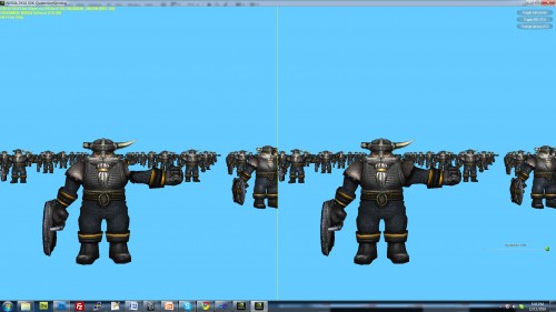
Skinning on GPU using a vertex shader. In this NVIDIA demo, the model on the right uses a real-time dual-quaternion skinning method that preserves the volume of the character's shoulder.
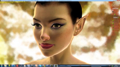
Real-time blend shapes on a GPU. Here, using a vertex shader, the GPU is doing the vertex deformations that interpolates the character's vertices between blend shapes.
Projection
Going back to our analogy about placing a camera and taking a photo. Now we need to do a “projection”, which in layman terms is basically, “what does the camera see?”
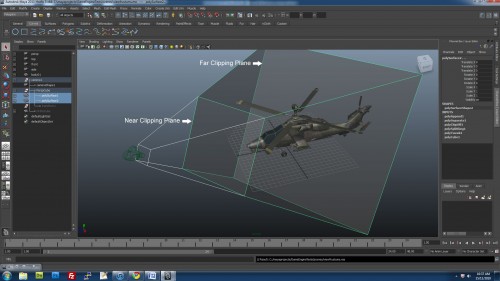
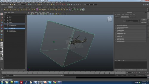
In computer graphics, we do this by defining what’s called a “view frustum”. A “frustum” is a pyramid with the top chopped off. With a view frustum, anything inside the volume of the frustum is drawn. Everything outside is excluded or “clipped”. In the camera settings in a 3D application, you typically have settings for “Near” and “Far” clipping planes. These are the near and far planes of the view frustum. The left, right, top, bottom planes can all be defined by mathematical means by setting a Field of View angle (also typically in your camera settings tab).
There are two types of projections typically used: Orthographic and Perspective. In orthographic view, there is no concept of a vanishing point. It’s great for top, side, front viewports, but it’s not realistic. For orthographic views, the view frustum is a box, where the top and bottom planes are parallel, and likewise the left, right are parallel and the near, far.
For perspective view, the view frustum looks like a truncated pyramid. When the computer projects the scene onto a view plane, it takes the far plane and squishes it so that the frustum ends up having parallel planes (like the orthographic frustum). This operation distorts anything that is further from the camera and makes them appear to be smaller than they are, which is how it achieves a perspective view.
Clipping
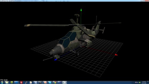
There’s no point in doing calculations for objects that aren’t seen, so we need to get rid of anything that is not in the view volume. This is harder than it sounds, because some objects/polygons may intersect one of the view planes. Basically, the way we handle this is by creating vertices for the polygons at the intersection points, and getting rid of the rest of the polygons that won’t be seen.
Screen Mapping
All of the operations that we’ve done above are still in 3D (X, Y, Z) coordinates. We need to map these coordinates to the viewport dimensions. For example, you might be running a game at 1920×1080, so we have to convert all the geometric coordinates into pixel coordinates.
Rasterization
At the end of the day, all we’re interested in is displaying a 2D image. That’s where “rasterization” comes in.
A raster display, is basically a grid of pixels. Each pixel has color values assigned. A “frame buffer” stores the data for each pixel.
We take our 3D data which is mapped to screen space coordinates, and we’re going to do some brute force calculations to figure out what color each pixel should be:
- At each pixel, figure out what is visible.
- Determine what color the pixel should be.
Many of the ideas behind scan conversion were developed in the early days of graphics, and they haven’t fundamentally changed since then. The algorithms are fast (enough) and many hardware manufacturers have embedded the algorithms into physical silicon to accelerate them.
In graphics, we use the term “Scan conversion” and “rasterization” fairly interchangeably as they kind of mean the same thing. The line drawing and polygon filling algorithms use the idea of “scan lines” where we process each row of pixels at a time.
Some of the things you do at Scan Conversion:
- Line drawing
- Polygon filling
- Depth test
- Texturing
Line Drawing
Line drawing is one of the most fundamental operations as it lets us draw things like wireframes on the screen. For example, based on 2 end points of a line, which pixels do you light up? A popular algorithm that’s been used for decades is the Bresenham Line Algorithm (http://en.wikipedia.org/wiki/Bresenham’s_line_algorithm).
Polygon Filling
Polygon filling is another interesting challenge. Based on a polygon definition, how do you figure out which pixels to light up that is ‘inside’ the shape of the polygon? A popular algorithm for this is the scan-line method. Google “scan line polygon fill algorithm” for more detail. You’d be surprised at how much brute force calculations are used for this kind of thing, hence why these algorithms were among the first to be hardware accelerated.
Depth Testing
Typically in a scene, you’ve got objects in front of each other. So we need to do some kind of a “depth test” where we only draw whatever is closest to the viewer. This is basically what depth-testing is. You may have already heard of something called a “Z-buffer”. There’s a similarity here. We have all our vertices and polygons in 3D, so we have a Z (depth) value for them. Based on this, we can determine the closest object to draw at each pixel.
Texturing
Rasterization is also where Textures are applied. At this stage, basically what we do is ‘glue’ the pixels from a texture onto the object. How do we know which pixels on the texture to get our color information from? From a UV map. That’s why we need UV’s. I’ll talk more about texturing and UV’s in more detail in a separate article.
Basically what it’s doing is mapping from the device coordinate system (x, y screen space in pixels) to the modeling coordinate system (u, v), to the texture image (t, s). Artists create UV maps to facilitate this projection, so that during rasterization, it can look-up what pixels to read color information from.
Texture Mapping was pioneered by Ed Catmull in his PhD thesis in 1974.
Pixel Shading
During rasterization, we can also do something called Pixel Shading. Like vertex shaders, a pixel shader is simply a program in the form of a text file, which is compiled and run on the GPU at the same time as the application. Specifically, the pixel shader will run the program on each pixel that is being rasterized by the GPU. So…just to recap: Vertex shaders operate on vertices in 3D space. Pixel shaders operate on pixels in 2D space.
Pixel shaders are important because there are many things that you want to do to affect each individual pixel as opposed to a vertex. For example, traditional real-time lighting and shading calculations were done per vertex using the Gouraud Shading Algorithm (http://en.wikipedia.org/wiki/Gouraud_shading). This was deemed ‘good enough’ and at least it was fast enough for older generation hardware to run. But it really didn’t look realistic at all, so you really wanted to do a lighting calculation at a specific pixel. With the advent of pixel shaders, we can now run per-pixel shading algorithms such as the Blinn-Phong shading model (http://en.wikipedia.org/wiki/Blinn%E2%80%93Phong_shading_model).
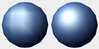
Per-vertex lighting (left) vs per-pixel lighting (right). Notice how the per-vertex lighting model doesn't result in a smooth highlight.
Another thing to point out about pixel shaders is that they can get information fed to them from vertex shaders. For example, in the lighting calculations, we needed certain information from the vertex lighting calculations done in the vertex shader.
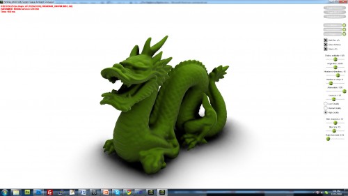
This combination of vertex and pixel shaders enable a wide variety of effects that can be achieved. For example, real-time ambient occlusion:
Conclusion
This has been a very high level overview of the real-time rendering pipeline. We’ve covered a lot of ground in this article, but I’ll admit that I’ve skimmed over a lot of information as there’s just too much to cover in an overview article.
When you look at the amount of work that is happening above, it’s hard to believe that all of this is happening on your computer (or cell-phone) so quickly. Literally thousands of calculations are happening in a split second, which enables us to have the interactive graphics that we have today.
To finish off, here’s a demo from NVIDIA showing off DirectX 11:
References:
Akenine-Moller T, Haines E, Hoffman N, 2008, Real-Time Rendering, Third Edition, AK Peters.
Shirley P, Marschner S, 2009, Fundamentals of Computer Graphics, Third Edition, AK Peters.
Hearn D, Baker M, 2004, Computer Graphics with OpenGL, Third Edition, Pearson Prentice Hall.
Angel E, 2009, Interactive Computer Graphics: A Top-Down Approach Using OpenGL, Fifth Edition, Addison Wesley.


